Links to stuff on this blog

Use the Site Index of Projects page link above for an easier way to find stuff on my blog that you might be looking for!

Sunday, June 26, 2011

GD&T Basic(s) True Position and Tolerances

This post is a very simple explanation of Position as used in Geometric Dimensioning and Tolerancing. Why am I writing about Position? One of the most frequent questions people ask me regarding Geometric Dimensioning and Tolerancing is "what does that target bulls-eye symbol mean". That bulls-eye symbol is called Position and it seems to be the most confusing and mysterious symbols in GD&T for some people. Before I talk about Position you should go back and read - or read if you haven't read already - THIS post that I wrote about tolerances and size and maybe even THIS post I wrote awhile back. There is nothing really mysterious or even complicated about the concept of Position and how it's used with Basic Dimensions in GD&T. The application can get pretty scary and complicated sometimes but the concept is pretty straight forward. I'm going to try and explain it in a overly simple way and later tie all these Design Related posts together as I write more of them.
 
Square Tolerance Zones
The first thing that is important to point out is that Geometric Dimensioning and Tolerancing is all about the dimensions tolerances so I'm going to compare the 'traditional' method of tolerancing to Position as a starting point. So to start with have a look at a 'traditional' drawing below that uses linear coordinate dimensions. On a 'traditional' drawing that is using linear dimensions the tolerances are put on each of the dimensions either directly as in the picture below or in the title block (or notes) on the drawing. Have a look at the below drawings 2A and 2B that are dimensioned 'traditionally' with the tolerances on the dimensions themselves. I have left the dimensions of the block itself off the drawing for clarity.

Linear Dimensions with a Square Tolerance Zone
  
In the top view of the above picture (2A above) there is a rectangular block and a couple of dimensions to a point near the middle. Imagine that you want to drill a hole 1.5 inches from the left side and 1 inch from the top as the dimensions show. Note that each dimension has a tolerance of +/-.25 inches so to get the hole in the right spot you first measure down from the top of the block 1 inch +/- .25 inches, giving you a total tolerance of .50 inches. Same thing with the other dimension, measure from the left 1.50 inches +/-.25 inches - again giving you a total tolerance of .5 inches. To get the hole in the right spot according to the dimensions (and the tolerances) you would have to drill the hole so that the center of the hole was somewhere inside that .5 inch square tolerance zone. Does that make sense? It seems strange if you think about it that a round hole would be positioned in a square tolerance zone doesn't it? Read more and this will start to make sense...

Saturday, June 18, 2011

GD&T: Maximum and Least Material Condition, Size Matters

Geometric Dimensioning and Tolerancing or GD&T is a subject that I get asked about frequently. As I wrote before in THIS post about Levels of Control I thought that I would Blog about the subject because I spend quite a lot of time answering friends a colleagues questions about it. Have a look at that post and read the fist couple of paragraphs if you are curious about what Geometric Dimensioning and Tolerancing is.
  
Size matters and size is what I want to write about in this post. After all having parts that are the right size is what allows them to fit together. What I am going to write about in this post might seem completely theoretical and somewhat pointless in the real world but it isn't. These concepts don't seem practical when you have a drill or a saw in your hand but actually this is all about having parts that you design and build fit together right? Fitting together of course is all about the size of the parts. Geometric Dimensioning and Tolerancing has some basic concepts about size that might seem a bit odd at first but it all makes sense when you think about how small a hole can be and how big a pin that has to fit in the hole might be - and then grab a hammer to force it into the hole.
  
The first point that I want to make is that all dimensions on drawings have to have a tolerance associated with them. All dimensions on drawings have to have some tolerance placed on them because it’s not possible to make something exact in the real world. If you ask someone “cut that thing into three 1 inch long pieces” you won’t get three exactly 1 inch long pieces. They might all be really close to 1 inch, but not all of them will be exactly 1 inch because exactly is a difficult thing to achieve. How do you know if they are all close enough to 1 inch for whatever you need them for? That’s where the tolerance comes in, it sets an upper and lower limit or a range on what is acceptable as a 1 inch piece for a particular application. Sometimes it might have to be really really close to 1"  and the tolerance will be really small, other times it might not matter much and the tolerance can be a lot. That’s the concept anyway and you can apply that to not only dimensions but also other more abstract things like shapes. “Is this thing flat enough?” “is this square piece of metal square enough?” etc.. of course ‘square’ and ‘flat’ will have to have some number associated with them (and a way to measure them) and that number will have a tolerance.
  
A Part Made Exactly To The Drawing
 
The reason that I am mentioning this is because in mechanical drawings the tolerance on the dimensions plays a big part in what the final product looks like and whether or not it’s going to work. The tolerances control what the shape of the part is or can be and they are just as important as the dimensions themselves. In fact it shouldn't be too surprising to read that in Geometric Dimensioning and Tolerancing it’s all about the tolerances! To get an idea of what I am talking about have a look at the picture below of the square thing with the hole in the center. I have left a few dimensions out of the drawing for simplicity and to explain the concept so don’t worry if it looks incomplete.


Saturday, June 11, 2011

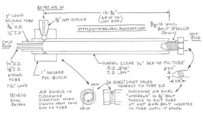
Homemade Ranque Hilsch Vortex Cooling Tubes: FAQ


One of the most popular things that I have done and blogged about is the Ranque Hilsch Vortex Tubes that I built. I get a lot of emails asking a lot of questions about RHVT’s and how to build them. There are no easy cut-and-dry answers to most of these questions because there are so many variables involved when building one, but there are some generalizations that can be made. Recently I decided to put together a FAQ page and with the help of a colleague and on line collaborator: Théo M. we have tried to answer some of the questions people have asked me. I am not at all an expert on these things and only know what I know by reading information online and from my own experiments. If you are planning on building one of these please look around at all the information the net has to offer and by all means contact me if you have any questions. At the end of this post I have placed some links that I have found useful.
  
As always when working with anything potentially dangerous (like compressed air) always wear appropriate protective gear like safety glasses and know what you are doing. If there are any questions that you may have that are are not in this FAQ or not answered clearly please email me at ottobelden@yahoo.com or leave a comment and I’ll be happy to answer you!

  
Homemade Vortex Tube Instructions from THIS post
   
If I get more questions in emails and comments on my blog I'll answer them below in this post and update the date below. I'll highlight any new info in the post so it will be easy to find.

FAQ UPDATED: 7/21/11

Check back often if you are curious or after you ask me a question. I'll answer you directly and add your question and answer to this post. Continue reading for the FAQ's and links!


Sunday, June 5, 2011

Geometric Dimensioning and Tolerancing (GD&T) Introduction

As a mechanical person I get asked a lot of questions about drafting, mechanical drawings and Geometric Dimensioning and Tolerancing or GD&T. I have written emails over the years  to friends and colleagues explaining some of the concepts and recently I have begun to help some folks learn it from scratch. Because of this I have decided to start writing some posts about this topic for some of the following reasons. One reason is this blog is about the things that I am doing and GD&T is one of the things that I do as a mechanical designer. Another reason for writing about this topic is the same reason I had in creating this blog: People ask me what I'm doing and building and it's easier to answer them in a blog post and let them all read about it in one place rather than me emailing a bunch of people over and over again. Also I'm writing about this topic because this is my blog I can do whatever I want
;-)
  
As I write more posts about this topic they are not going to come in any particular order and are not really intended to be a instructional course, they are just answers to questions that I get. As always with anything that I write about if you have any questions you can email me at ottobelden@yahoo.com or leave a comment. I'll be glad to answer any questions that you may have.
  
Geometric Dimensioning and Tolerancing
 
If you are interested in and not sure what Geometric Dimensioning and Tolerancing (GD&T) is check out this link HERE on Wikipedia. There is a general overview of GD&T and a neat interactive chart that is fun to play with. I'll summarize the topic generally by saying that GD&T is a language of mostly symbols used on mechanical engineering drawings that communicates the design intent to a person who is using the drawing to make something. GD&T is a international standard (or several actually) that controls all the physical aspects of what the drawing is describing in a single, concise and unambiguous way. From the drawing you should not only be able to make something but you should also be able to check and measure the thing that has been made to see if it's correct. Specifically Geometric Dimensioning and Tolerancing is a way to use dimensions to describe exactly what you want a thing to look like when it's made and how much that thing can deviate from exactly perfect and still be correct. The reason for this is you can draw something perfectly flat, round, 6 inches long etc...  but when it's actually made it can never be EXACTLY those things. Even machines can't cut or shape something to be exactly perfect, there has to be a tolerance with every dimension. For example, how much out of round is OK? How warped and not flat can a surface be? How much longer or shorter than X inches is OK? How do I read the drawing in a way that lets me check the parts dimensions? How do I know if the thing I am drawing will fit together with something else? Geometric Dimensioning and Tolerancing answers those questions and a lot more.