Hello!
Yes I know that I said in my last post that I wasn't going to post again in Blogger... I decided to post one last time because of several emails that I have received about why I am done with the New Google Interface and Google in general. Here is why I hate Google and the Blogger interface that they have destroyed.
I'm not going to elaborate much so here is the simple explanation in no particular order:
1) The New Interface Is Hard To Read: The new Google interface is all white space with black text making it hard on the eyes especially in low light, which is how I like to use the computer in the evening. I can't easily see what I am typing. The eye strain is obvious (unless you work for Google). Why do this, let's make it hard for everyone to read!!!!!
2) The menus are down the left side instead of across the top, a very unnatural place to look for stuff. Don't we all gravitate to the top of the window to look for "File" or "Edit" or any other common task? It's become natural to scan the top of the page or window to look for the options that are available... let's "Save" what we are doing (look to the top of the window); "Edit" the text or font (look to the top of the window)... Or... "I want to do something... it should be in the Tool's menu.... at the top.... where the hell is it????... not at the top!!! It's down the side!!!".... Why???
3) All the menu selections are now different. OK I get it, lets take what used to be at the top and put it down the left side of the window... But wait, you didn't do that did you? What used to be a simple click at the top is now buried in some complicated maze of stupidity in your "improved" left hand side bar menu system. Why?? Please tell me why you would do this?
4) Login page. The "blogs I follow" info is bigger and takes up more screen space than my own blog information when I log in. Why is that? Did I log in to see what my buddies are writing or did I login in to create a new post. This is after all about what I want to write about.
Google think tank: "Let's put all the stuff our user's friends are writing about on our users home page because we think our user wants to see that"... When I log in I want to see what is going on with my blog first, everyone else can wait until I'm ready to click on something (CLICK AT THE TOP) and see what other Bloggers are writing about.
Why can't I see on my own login page my own Blog info? Why???
- Side note: Blogging is a Web Log about me (or you) want to write about. Blogs that I follow are secondary, in other words when I log in TO MY BLOG I expect to see info about MY BLOG and not other people, I can and will get to them later (Unless I use a Google product, because then I have to see everything BUT then things I want to see).... WHY?????
5) Scroll bar and Omnibar. Do you use Google chrome? Good luck if you do. Chrome has a very stupid and annoying scroll bar that is inverted in relation to every sane person in the world (unless you are a idiot). The scroll bar is "dark" where you have to click to scroll, exactly backwards from every other software product I have ever used.
Here is what this amounts to:
Google engineer says " Lets be different and mix it up a bit, lets invert the colors on the scroll bar, everyone will love it"...
A real world example: "Let's reverse the gas and brake pedals in the car we are building, everyone will love it"
Insert frustration, car crashes, cuss words and...
6) The Google Omnibar.... lets not even talk about it.... one word: WHY????? Fill in for me what I typed yesterday??????? REALLY????????
7) Another thing about Google and in this case Andriod... Here is an example from my phone right now:
Today is Thursday July 5th at 5:11pm
My phone's call Log says I had a call: "incoming call - 2 days ago" When I click on that call the call details say the call was actually made on Sunday July 1st at 8:42pm.
So in other words the call wasn't received "2 days ago" it was received 5 days ago. The call log is wrong! Thanks Google!
This makes the call log useless for me. I have to open the call log and click on Details for every call to see when it was actually made if I want to know when a call was placed or received.
So am I upset at Google, am I upset at Andriod??? AM I upset at both?? Is the new Google Blogger interface all that bad?
Maybe... or maybe it is just me. If the user interfaces for Google products actually made sense to someone like me, an average user, then I could accept the change and improvements with all their bugs and problems...
Unfortunately this isn't the case. Google has across the board created an online environment isn't user friendly, is overly complex to use for what it does and all around "broken what didn't need to be fixed".
Blogger wasn't perfect my any means but now it is trash thanks to the Google team 'Improvements'. Honestly if Goggle had come in a simply fixed what was wrong with Blogger (a few minor tweaks) I would be right there with them cheering them on, even if there were a few bugs.
But because Google decided to change everything and in the process mess up things that used to work, change around menus that were easy to use, move simple "one click" tasks down to places I don't want to click... and gave me a phone that has a useless and messed OS... instead of making things easier, rather they have made things harder...
Because of everything they have done, I am done with Google.
Showing posts with label Robotics. Show all posts
Showing posts with label Robotics. Show all posts
Thursday, July 5, 2012

Sunday, February 6, 2011
Free Energy and Bad Pot
I have more or less finished moving and unpacking everything and I decided to rest a bit and do something relaxing like fix a broken power supply! I decided to fix this not because I need the power supply right now, or because I found it in the garbage 2 days ago but because there is nothing better to motivate you to unpack as having the need to find something. For example: my soldering iron and digital volt meter. Both of which I had to use to fix the power supply and in the process of finding them I found other useful stuff too - like toenail clippers!
The power supply that I found is an Extech 382200 that has a 0-30 volt output and up to one amp. Both the voltage and the current are adjustable so this is a handy thing to have. When I plugged this thing in and turned it on the voltage display read 51.1 volts! That is a bit higher than the 30 volt rating and the voltage adjustment knob didn't do anything.
 |
| EXTECH Power Supply (broken) |
At first I thought that the output transistors might be shorted so they were the first things that I checked. If the transistors short then the output usually goes higher than what it's supposed to be and it's not adjustable - of the fuse blows. The transistors are mounted to a big heatsink on the back of the power supply but to get at them I had to take the cover off. Check out the picture below!
Sunday, November 21, 2010
Arduino Controlled Biped Robot
This week I have spent some time in the garage and a lot more time on the computer. The garage time has been spent rebuilding a biped robot built by Auzieman. He has a great site that is devoted to homemade robotics and everything related to building and programming them. This particular robot is a biped that uses six Futaba S3003 servos controlled by an Arduino board. The power supply is connected via an umbilical to save weight. The task that I have undertaken is refining the mechanics and making everything a little less loose! Think of it as a robotic 'shave and haircut'.
 |
| Arduino Controlled Biped Robot |
The concept here is to build a robot that uses mostly similar or exactly the same brackets and servos to save cost. Developing a universal bracket that mounts Radio Controlled style servos is a difficult task due to the shape and size of RC servos. These types of servos are meant to be used in model cars and boats and not specifically as structural elements so they have very limited mounting points on one side only. A universal bracket then has to 'wrap around' the servo and provide holes/surfaces to mount whatever you dream up.
Wednesday, December 30, 2009
Tamiya 1/16 Scale Leopard Chassis....
I have a couple of updates relating to robotics to share this week. Below is a picture of a Tamiya 1/16 scale model tank that was given to me as a gift. It is actually one tank with the upper plastic tank looking parts on the right and the metal mechanical motorized chassis on the left. I want to thank my friend DV here for giving it to me - Thanks!
Looking at it in detail it is clear that this is a quality kit but it has seen better days. The metal treads are not rolling smoothly and the tread tension adjustment is maxed out and the treads are still loose (maybe they have a few too many links!) There is also some missing screws and other things that at first glance I thought were missing parts but now I believe they were removed in an attempt to make this thing go.

The drive mechanism for this is pretty sophisticated considering that it is a model. There is one drive motor that is running all metal gears that is connected to two mechanical clutches (black cylinders in the picture). The clutches are activated by a servo (missing in this tank) similar to the servos that I used in My Robot.
The really neat thing about this kit and what really caught my eye initially is the quality of the gearbox and the fact that most of the entire chassis is metal. The suspension for the treads actually works with each idler wheel in the tread being supported with a torsion spring. Additionally the plastic top seems to have amazing detail and a 'real' look to it. I'm not a tank expert but it appears that everything looks right...
These days I'm not spending a lot of time in the freezing cold garage where I can work on this but as soon as the weather warms up a bit (or at least the garage) I'm going to carefully photograph the entire chassis, gears etc... strip it down, clean it, paint and re-assemble it all to at least the point that it's at now. The action of the clutches seems to be really stiff and it needs a lot of work but I think that this is the beginning of a really cool project. I'm not sure if I'll rebuild it as a tank but I will figure it out and get it running.

On a similar and related note my son built up a tank as well as you can see in the second picture. He got his designed and 'running' in a matter of several minutes! Similar scale but it has a much more flexible architecture!!
As my son works on his vehicle I'll work on mine and post the progress of each as they progressively progress onward....
Saturday, October 24, 2009
The Robot Walks On Carpet
Here is another video of the robot walking! Wow exciting! Well not really but there are a few things that are different between this video and the last couple that I have posted. The first thing that is new is I broke down and bought a new camera... I really needed a new camera. The digital camera that I have been using was originally purchased from an Egyptian Pharaoh, second hand right outside his pyramid so it was old but in good condition! The new camera was on sale, has sound and is much better resolution. So no more fuzzy dark silent movies that you can't see anything.
The other thing that is different is the robot is walking on carpet. This may not seem like a big deal but it is really (to me). Up until now the contraption has been stumbling along on a rubber mat to add some friction to the feet. Trying to walk in carpet didn't work very well because the feet tended to get hung up in the threads of the carpet. Well messing with the speed and the leg positions overcame that problem so now it can walk on the carpet. There are still some issues to be worked out to get it to walk straight but I know what is going on with that so it's just a matter of fixing it.
The last video is the initialization of the servo motors and the legs running through the walk cycle. Looking closely I think I see a problem in the speed changes not being sent to the board and some timing in the commands being executed. More stuff to fix in the code.
This is an ongoing project that is being done in a 'make it up as I go along' style. Now that I have it walking I want to make it turn, change speeds etc... but adding sensors and a stand alone controller board so I'm not tethered to my laptop are the next big things. Stay tuned....
The other thing that is different is the robot is walking on carpet. This may not seem like a big deal but it is really (to me). Up until now the contraption has been stumbling along on a rubber mat to add some friction to the feet. Trying to walk in carpet didn't work very well because the feet tended to get hung up in the threads of the carpet. Well messing with the speed and the leg positions overcame that problem so now it can walk on the carpet. There are still some issues to be worked out to get it to walk straight but I know what is going on with that so it's just a matter of fixing it.
The last video is the initialization of the servo motors and the legs running through the walk cycle. Looking closely I think I see a problem in the speed changes not being sent to the board and some timing in the commands being executed. More stuff to fix in the code.
This is an ongoing project that is being done in a 'make it up as I go along' style. Now that I have it walking I want to make it turn, change speeds etc... but adding sensors and a stand alone controller board so I'm not tethered to my laptop are the next big things. Stay tuned....
Sunday, October 18, 2009
Robot Experimental Walk Cycle First Attempt
This weekend I finally hat the time to mess around with the robot some more and I managed to get it to walk. It still isn't as smooth as I would like but it does walk! I'll start this blog entry with a couple videos of it doing it's thing.
From the video you can see it stumble along the floor on a piece of rubber mat that I set on the carpet. The rubber gives it's 'feet' some traction because it was getting hung up in the carpet, and /or slipping and sliding on the hardwood floor. I suppose the obvious solution would be to put rubber tips on the feet but the rubber mat was easier for now. The legs and feet are made from 0.17" diameter carbon fiber tube and there is no traction on wood and the ends of the tube get caught in the carpet. A long term solution will be to put some rubber or other type of material on the ends of the tube.
The walk cycle that the legs are running through is just a pattern that is repeating and a rather rapid rate. I found that running it slow is actually more unstable than at a faster rate. A couple of things that I am going to play with are the speed that the servos are running and the center of gravity. Changing the speed will be a software change and lowering the center of gravity will mean cutting the legs shorter. I could lower it by adding some weight to the robot base underneath the robot but the increase in overall weight would strain the servos too much.
What follows is a detail of the leg motions that I am using right now to make it move and a picture to help explain it. The rectangle at the top is showing the top view of the robot with each leg location 1 through 4. The bottom rectangle shows a side view with some colored arrow boxes. The letters in the boxes indicate locations of the feet relative to the base of the robot.
So if you look at the colored box on the right it's showing the feet positions of legs 1 and 4, and the colored box on the left is showing the feet positions of legs 2 and 3. As you can see from the box moving a foot from position 'a' to position 'b' is raising the foot up. Moving from 'b' to 'c' is moving the foot away from the base while it's up off the floor, and moving from 'c' to 'd' is setting the foot down at a distance from the base.

Additionally there are some colored arrows in the boxes that indicate the order in which the feet are moving through these positions. The blue arrows indicate motion that a foot is doing all by itself and the orange arrows show the motion that all the feet do together at the same time. Here is what is happening to make the robot walk with all the legs (feet) starting at the 'a' positions:
Move Leg 1 from 'a' to 'b' to 'c' to 'd'
Move Leg 4 from 'a' to 'b' to 'c' to 'd'
Move all the legs together:
Legs 1 and 4 move to their 'a' positions while legs 2 and 3 move to their 'd' positions
Move Leg 2 from 'd' to 'c' to 'b' to 'a'
Move Leg 3 from 'd' to 'c' to 'b' to 'a'
At the end of the above motions all the legs are back to their 'a' positions and the robot has moved about 1.5" forward. Right now that is all it can do but that is enough for now. Each of the legs also has a Turn servo that isn't being used yet. I want to get the walking forward part completely figured out and smooth, then I'll work on walking backwards and hopefully turning after that.
Anyone interested in the Python code I wrote to make this work let me know and I'll post it.
Sunday, October 11, 2009
More on the home made robot... starting to walk
After a long weekend I finally got the Python code to work the way I wanted it to and I am able to more easily control the motors. Most of my time over the last several days has been spent figuring out how Python works and not really messing with the robot motion directly. Because of that I'm tired and don't have the time to get a really smooth walking motion today. What I currently have does work but it jerks along the floor and doesn't make the 'forward motion' that it should be doing based on how much the legs are actually moving. I do count this as some success because it should be easier from where I am at now to get it to at least walk.
What you can see from the video is that all 4 of the legs are moving in cyclical 'walking' motions but they are not coordinated enough to really get the robot to move forward. This is because at a few points in the cycle some of the legs are moving forward and others are not. So when it's trying to walk on the floor the legs that are not moving are being dragged along!!! Oh well like I mentioned I have spent all my energy getting the code to work and not on actually the motion.
The progress that I did make this weekend was I managed to figure out how to use the import statement in Python to bring in a chunk of code that defines some custom commands that I wrote. What that means is now I can write a script like this:
PS.ServoPos(6,2200)
PS.ServoPos(7,4300)
time.sleep(.2)

Below is the Python code that I wrote to help with the programming of the Pololu board. The Pololu requires position commands that range from 500 to 5500 to position the motors. When sending the position to the Pololu board you have to take a position like 3800 and convert it into 2 bytes of data with the Most Significant Bit of each of those two bytes set to 0, shifting bits around as needed.
Anyway doing that by hand is a pain so I wrote the program below to do it for me. This was handy when figuring out positions that I wanted to have defined in the function calls that I wrote.
# Pololu Range Converter
# Written By Otto Belden Oct 2009
# http://ottobelden.blogspot.com/search/label/Robotics
# This will take a input from the console and print out the
# high and low byte that the Pololu needs to position the servo
# with the MSB of each of the two bytes 0 as required by Pololu
#
import sys
# Set a default position
pos = 2500
while pos != 0:
pos = int(raw_input("Give me a number or 0 to exit "))
if pos == 0:
print "Exiting..."
break
# get the data 1 byte (high byte)
data1 = (pos-(pos&127))/128
# get the data 2 byte (low byte)
data2 = pos&127
print " Position = ", pos, "High Byte = Ox%x"%data1,"Low Data = 0x%x"%data2
The progress that I did make this weekend was I managed to figure out how to use the import statement in Python to bring in a chunk of code that defines some custom commands that I wrote. What that means is now I can write a script like this:
PS.ServoPos(6,2200)
PS.ServoPos(7,4300)
time.sleep(.2)
So what is going on in the above code is I can just directly address the particular motor I want and send it to a particular position. For example the first command PS.ServoPos(6,2200) is sending servo number 6 to position 2200 !!! WOW! I'm sure all you Python gurus out there are laughing at me but considering I'm not a programmer and I have only been using Python now for 12 days or so it's an accomplishment.
Here are the steps that I listed in my Last Post that I wanted to get done with updates to each:
1) figuring out a clean way to mount the Pololu board to the robot base with it's one mounting hole
I mounted the board and made a strain relief for the cables (see picture below)
2) cable management to make sure the servo wires don't get all tangled up while it's running
2) cable management to make sure the servo wires don't get all tangled up while it's running
I can't say that they are under control but the cables now don't get tangled!!! (see picture below)
3) using the jog program to get the remaining leg hard stop values
3) using the jog program to get the remaining leg hard stop values
I got this done and wrote a little converter program to help (see source code below)
4) hours of coding and testing to make this thing walk!!!
4) hours of coding and testing to make this thing walk!!!
When I wrote hours of coding and testing I was underestimating the task... lets say DAYS of coding!

A picture of the Pololu board mounted to the Epson Printer Base that I cut up and turned into the robot base. The black plastic on top of the board with the wires coming out of it is a piece of 0.04" thick ABS plastic that I cut and screwed to the base. There is a second piece of ABS as well that is sandwiching the wires in there with some rubber bands to hold it together. It's not elegant but it works to keep the Futaba servo connectors from being pulled or worked off the Pololu board while the robot is running.
The next thing to do at this point is refine the walk cycle to get all the legs to move together so it can walk instead of dragging its feet along the floor. As soon as I get that done I'll post another video of it walking.
Below is the Python code that I wrote to help with the programming of the Pololu board. The Pololu requires position commands that range from 500 to 5500 to position the motors. When sending the position to the Pololu board you have to take a position like 3800 and convert it into 2 bytes of data with the Most Significant Bit of each of those two bytes set to 0, shifting bits around as needed.
So 3800 decimal =
00001110 11011000 binary
which then has to be converted to
00011101 01011000
which is equal to two bytes of
0x1D 0x58
# Pololu Range Converter
# Written By Otto Belden Oct 2009
# http://ottobelden.blogspot.com/search/label/Robotics
# This will take a input from the console and print out the
# high and low byte that the Pololu needs to position the servo
# with the MSB of each of the two bytes 0 as required by Pololu
#
import sys
# Set a default position
pos = 2500
while pos != 0:
pos = int(raw_input("Give me a number or 0 to exit "))
if pos == 0:
print "Exiting..."
break
# get the data 1 byte (high byte)
data1 = (pos-(pos&127))/128
# get the data 2 byte (low byte)
data2 = pos&127
print " Position = ", pos, "High Byte = Ox%x"%data1,"Low Data = 0x%x"%data2
Saturday, October 3, 2009
Robotic Leg Testing with Python, Pololu and some good luck...
A day or so ago I got my Pololu USB 16 RC Servo Controller board in the mail. This is a USB or serial controlled RC Servo controller that can handle up to 16 RC Servo motors simultaneously. The board takes serial data from either the standard mini USB connection or a RS-232 connector and turns it into the pulse train necessary to position the RC servos. The handy thing about this board (and other like it) is that the board takes care of the pulse generating and all you have to do is sent it a serial string of data to tell it which motor goes to what position - the board takes care of the pulses.
For my initial mechanism testing I built a little test box that had an oscillator and three 'one shot' pulse stretchers that I could control with potentiometers to get the desired pulse train. That was good enough to test the mechanism one part at a time but for the coordinated motion required for exciting robotic action I need something like the Pololu USB 16. Because my robot has 3 servos per leg and a total of 4 legs I need to be able to control 12 servos and the Pololu handles 16... so far so good with 4 to spare....
My initial impression of the Pololu USB 16 is that it's small and only has one mounting hole to mount the board. The small size is great but the single mounting hole will make it an interesting challenge to mount it to the robot base. The other thing that I noticed about it is the servo power connector wasn't soldered to the board itself when I got it. I decided to solder it to the backside of the board since on the component side it will cover up the silkscreen on the board and make it hard to connect the servos to the header. Not a big deal I guess. I didn't bother to figure out a way to mount it just yet, I thought I'd better test it first. So I just set it on the robot base and hooked it all up.
Sorry about the fuzzy picture but you get the idea.

Another nice thing about the Pololu is it comes with a driver that once installed lets the USB connection to the Pololu board look like a standard serial COM port on your computer. That way controlling the Pololu is done by sending serial data out the COM port (really the USB). This is handy because most computers, especially laptops these days don't have an actual serial COM port.
The first thing that I did to make sure that this was all working was write a simple Jog test program in Python. I'll post the code for this at the end of this blog post. The code is mostly mine with a bit of the data conversion stuff from an example on the Pololu website. I used this jogger program to incrementally move the servos to their mechanical stops. I had to do this because the travel on each servo is 180 degrees but my robot leg mechanism doesn't use all 180, mechanically the linkages wont go that far. Each time I moved the servo with the jogger program it prints out the actual servo position and once I was at the mechanical stops I wrote down that position for each servo. As long as I don't tell the servo to go past that position I won't 'crash' the robot mechanism into it's hard mechanical stops.
Once I had all the mechanical stop positions written down I wrote a simple 'exerciser' script that moves the servos through their ranges. This was not only to test the mechanism but also to help me figure out how Python programming works (I'm not a programmer). Also this allowed me to see how well the Pololu handles coordinated motion of multiple servos. I made a 28 second grainy and dark video of the leg running this script.
It looks like the Python code talking to the Pololu USB 16 board works pretty good at getting everything running at the same time. All three servo's ran as expected without crashing into anything and the motors run at the same time as opposed to stepping through each motion one at a time.
The next immediate steps in the robot development are going to be:
1) figuring out a clean way to mount the Pololu board to the robot base with it's one mounting hole
2) cable management to make sure the servo wires don't get all tangled up while it's running
3) using the jog program to get the remaining leg hard stop values
4) hours of coding and testing to make this thing walk!!!
Here is the Python code of the Jogger program that I wrote. I want to say again that I am not a programmer and I have only been writing Python code for 4 days now so it probably isn't the best example of how to do this - but it woks. If you are a Python Guru please let me know what I can do to improve my code especially if it will make the next programming task (walking robot) a bit simpler and easier for me. In other words HELP!!!! ;-)
Python needs to have everything indented correctly with spaces to run and the copy/past from Python IDLE seems to have removed some of those. You may have to tinker a bit to get it to work and look right in the Python editor but all of the code below works on my Windows Laptop running Python with the pySerial module loaded. PySerial gives you the serial commands to write out the virtual COM port (really a USB connection) that the Pololu USB driver sets up when you plug in the Pololu board.
The first thing that I did to make sure that this was all working was write a simple Jog test program in Python. I'll post the code for this at the end of this blog post. The code is mostly mine with a bit of the data conversion stuff from an example on the Pololu website. I used this jogger program to incrementally move the servos to their mechanical stops. I had to do this because the travel on each servo is 180 degrees but my robot leg mechanism doesn't use all 180, mechanically the linkages wont go that far. Each time I moved the servo with the jogger program it prints out the actual servo position and once I was at the mechanical stops I wrote down that position for each servo. As long as I don't tell the servo to go past that position I won't 'crash' the robot mechanism into it's hard mechanical stops.
Once I had all the mechanical stop positions written down I wrote a simple 'exerciser' script that moves the servos through their ranges. This was not only to test the mechanism but also to help me figure out how Python programming works (I'm not a programmer). Also this allowed me to see how well the Pololu handles coordinated motion of multiple servos. I made a 28 second grainy and dark video of the leg running this script.
It looks like the Python code talking to the Pololu USB 16 board works pretty good at getting everything running at the same time. All three servo's ran as expected without crashing into anything and the motors run at the same time as opposed to stepping through each motion one at a time.
The next immediate steps in the robot development are going to be:
1) figuring out a clean way to mount the Pololu board to the robot base with it's one mounting hole
2) cable management to make sure the servo wires don't get all tangled up while it's running
3) using the jog program to get the remaining leg hard stop values
4) hours of coding and testing to make this thing walk!!!
Here is the Python code of the Jogger program that I wrote. I want to say again that I am not a programmer and I have only been writing Python code for 4 days now so it probably isn't the best example of how to do this - but it woks. If you are a Python Guru please let me know what I can do to improve my code especially if it will make the next programming task (walking robot) a bit simpler and easier for me. In other words HELP!!!! ;-)
- Python Pololu USB 16 Servo Jogger Program -
Python needs to have everything indented correctly with spaces to run and the copy/past from Python IDLE seems to have removed some of those. You may have to tinker a bit to get it to work and look right in the Python editor but all of the code below works on my Windows Laptop running Python with the pySerial module loaded. PySerial gives you the serial commands to write out the virtual COM port (really a USB connection) that the Pololu USB driver sets up when you plug in the Pololu board.
# Pololu Motor Range Finder or Keyboard Jogger
# Written By Otto Belden Oct 2009
# http://ottobelden.blogspot.com/search/label/Robotics
#
import serial
import sys
#
#set com 3 up for communications Pololu defaults to com 3
ser=serial.Serial(2)
ser.baudrate=9600
# set the speed of Servo at something slow and reasonable with
# a varaible serstr = Serial String to write to com port
# Start DevID Command Servo Data1
serstr = chr(0x80)+chr(0x01)+chr(0x01)+chr(0x02)+chr(0x10)
ser.write(serstr)
# set a default position at a mid range position for the servo 2750
# which breaks down in Pololu speak to 0x15 0x3E Data 1 and Data 2
# a varaible pos = position
# then build a new Serial String using that position and send it out
pos = 2750
# Start DevID Command Servo Data1 Data2
serstr = chr(0x80)+chr(0x01)+chr(0x04)+chr(0x02)+chr(0x15)+chr(0x3e)
# define function newposition() that will calculate the 2 byte positions
# from the current position and assign those bytes to Data1 and Data 2
# then write out a new string
def newposition():
if pos <=700 or pos >= 5300:
print "******WARNING SLOW DOWN******"
# get the data 1 byte (high byte)
data1 = (pos-(pos&127))/128
# get the data 2 byte (low byte)
data2 = pos&127
# Start DevID Command Servo Data1 Data2
serstr = chr(0x80)+chr(0x01)+chr(0x04)+chr(0x02)+chr(data1)+chr(data2)
ser.write(serstr)
# print out to the console the instructions and keys to use then get keypresses
print "The servo should be on right now and in the middle of it's travel"
print "Use the '1' and '2' keys to jog the motor Forward and Reverse 100 counts"
print "Use the '3' and '4' keys to jog the motor Forward and Reverse 50 Counts"
print "Use the '5' and '6' keys to jog the motor Forward and Reverse 10 Counts"
print "Use the '7' and '8' keys to jog the motor Forward and Reverse 5 Counts"
print "Hit the '0' key to quit\n"
Input = 1
while Input != 0:
Input = raw_input()
Input = int(Input)
if Input == 0:
print "Now exiting last position was ",pos
ser.close() # close the com port befor exiting
print "Com port is open =",ser.isOpen() # make sure the port is closed
break
if Input == 1:
pos = pos - 100
newposition()
if Input == 2:
pos = pos + 100
newposition()
if Input == 3:
pos = pos - 50
newposition()
if Input == 4:
pos = pos + 50
newposition()
if Input == 5:
pos = pos - 10
newposition()
if Input == 6:
pos = pos + 10
newposition()
if Input == 7:
pos = pos - 5
newposition()
if Input == 8:
pos = pos + 5
newposition()
print "New Position = ",pos
# Written By Otto Belden Oct 2009
# http://ottobelden.blogspot.com/search/label/Robotics
#
import serial
import sys
#
#set com 3 up for communications Pololu defaults to com 3
ser=serial.Serial(2)
ser.baudrate=9600
# set the speed of Servo at something slow and reasonable with
# a varaible serstr = Serial String to write to com port
# Start DevID Command Servo Data1
serstr = chr(0x80)+chr(0x01)+chr(0x01)+chr(0x02)+chr(0x10)
ser.write(serstr)
# set a default position at a mid range position for the servo 2750
# which breaks down in Pololu speak to 0x15 0x3E Data 1 and Data 2
# a varaible pos = position
# then build a new Serial String using that position and send it out
pos = 2750
# Start DevID Command Servo Data1 Data2
serstr = chr(0x80)+chr(0x01)+chr(0x04)+chr(0x02)+chr(0x15)+chr(0x3e)
# define function newposition() that will calculate the 2 byte positions
# from the current position and assign those bytes to Data1 and Data 2
# then write out a new string
def newposition():
if pos <=700 or pos >= 5300:
print "******WARNING SLOW DOWN******"
# get the data 1 byte (high byte)
data1 = (pos-(pos&127))/128
# get the data 2 byte (low byte)
data2 = pos&127
# Start DevID Command Servo Data1 Data2
serstr = chr(0x80)+chr(0x01)+chr(0x04)+chr(0x02)+chr(data1)+chr(data2)
ser.write(serstr)
# print out to the console the instructions and keys to use then get keypresses
print "The servo should be on right now and in the middle of it's travel"
print "Use the '1' and '2' keys to jog the motor Forward and Reverse 100 counts"
print "Use the '3' and '4' keys to jog the motor Forward and Reverse 50 Counts"
print "Use the '5' and '6' keys to jog the motor Forward and Reverse 10 Counts"
print "Use the '7' and '8' keys to jog the motor Forward and Reverse 5 Counts"
print "Hit the '0' key to quit\n"
Input = 1
while Input != 0:
Input = raw_input()
Input = int(Input)
if Input == 0:
print "Now exiting last position was ",pos
ser.close() # close the com port befor exiting
print "Com port is open =",ser.isOpen() # make sure the port is closed
break
if Input == 1:
pos = pos - 100
newposition()
if Input == 2:
pos = pos + 100
newposition()
if Input == 3:
pos = pos - 50
newposition()
if Input == 4:
pos = pos + 50
newposition()
if Input == 5:
pos = pos - 10
newposition()
if Input == 6:
pos = pos + 10
newposition()
if Input == 7:
pos = pos - 5
newposition()
if Input == 8:
pos = pos + 5
newposition()
print "New Position = ",pos
Tuesday, September 22, 2009
Robot Base Mechanics
Finally after much filing, cutting and drilling the 4 legs are assembled to the robot base. As mentioned in other posts and to summarize here the base is made from an Epson printer cover and each leg is built from 3 Futaba S3004 (or in some cases S3003) servos. It took some time to get the whole mess to this point, mostly because of other life things getting in the way, but now that it is done (partially) I can take a break and focus on the electronics.

When positioned carefully the legs can support the weight of the assembly and be stable without falling over and without power. I am considering using this position as a generic starting position to power up from but having the base sit flat on the floor might be better. With the base sitting flat on the floor the challenge would be to get the legs under control and the entire thing to stand up. Once standing up of course getting it to walk without falling over would be next.

At this point there isn't a lot left to do mechanically other than routing the servo cables so the don't get tangled as the legs actuate. While I am doing that I'm going to be looking into servo controllers and the software needed to control them. Initially I'm planning on just having a "serial to servo" converter on the robot with an umbilical connecting it back to a computer and a power supply. I'll use that set up to debug most of the motion and work out walking. The eventual goal will be to have a processor board with batteries on the robot so it can move autonomously but until I can figure out how to make it move a remote PC to control it will be easier. Why do anything the hard way?
Sunday, September 20, 2009
More Legs and Some Progress ( or More Futaba Servos Assembled...)
This evening I have a bit of an update on the construction of the robot. It may seem like this is taking a long time to build but the project itself isn't taking too much time (all things considered) I'm just not finding a lot of time to work on it. I did manage to get all four legs built up. As mentioned these are using mostly Futaba S3004 and a couple Futaba S3003 Servos that are inexpensive and so far easy to use. The only difference between the Futaba S3003 and the S3004 is the 3004 have bearing and not bushings. Each leg consists of three servos in total giving each leg what I call Turn, Rotate and Extend motions. It's pretty irrelevant what I call each axis of motion but for now I'm sticking with those names. In the last update that I posted I had a picture showing the plastic base that I cut from the top cover of a desktop Epson printer.

This shows more or less how I intend to have the legs sit but there are only three legs in the picture. I am happy to say now that I have the fourth leg built up using the Futaba's and I also have all the turn brackets fabricated for all three legs that I mentioned in the Aye Robot post. Also I figured out a couple of issues in building up two of the legs as 'mirror images' of the initial prototype leg. Anyway here are all four if full color for your enjoyment:

As mentioned these are all using Futaba S3004 servos (mostly a couple of Futaba S3003's as well). The orange colored parts on the end are cut pieces of K'Nex that I used as bushings. There is a 4-40 screw holding a nylon spacer that runs in the center hole of the K'Nex acting as a bearing (bushing technically). On the bottom of each Turn bracket I mounted the round disc Futaba Servo Horn that comes with the Futaba in the box when you buy it. That servo horn will allow each one of the above legs to mount directly on top of yet another servo that is mounted in each corner of the 'hacked' Epson printer top. I took a picture to help explain a bit better what I mean.

In the picture you can see one of the Futaba S3003's sitting in the corner of the printer top that I'm now going to start calling something like 'robotic base chassis' instead of Epson printer top. Maybe 'Base Chassis' is better and shorter. Anyway on the bottom of the leg assembly you cab see the round Futaba Servo Horn screwed to the Turn Bracket with a couple of 4-40 screws. Immediately remaining at this point is cutting 3 more holes on the Base Chassis to mount the Futaba's in and figuring out a way to secure them in those holes. Right now I am thinking of cutting up the remaining pieces of the printer cover and gluing them onto the Base Chassis to provide screw points for the Futaba's.
I need to give it a bit more thought but maybe metal brackets would be better than glued plastic.
Monday, September 14, 2009
Update on the Robot Building
This post is just a quick update on the progress of the robot that I am building. I have been busy with other things recently and have not had a lot of time but some progress has been made. I managed to get the third leg assembly built and part of the plastic base modified to mount the first leg. The third leg that I built is a mirror image of the first tow because I need what essentially is a left and a right set of two legs each. These will be in opposite corners from each other. So in the picture below the upper left corner leg is the mirror image assembly of the other two legs.

At this point I need to complete the last 'mirror image' leg and continue modifying the base. In the picture the lower left leg is sitting on it's rotate base, eventually all the legs will get similar bases. Under each base an additional servo motor will be mounted that will turn each leg independently.
There is still a lot of work to do but the project is coming along... some open issues still are the 'walk cycle' that the legs will have to perform in unison allowing the contraption to move without falling over and a big issue of getting the electronics working. As far as the walk cycle goes I believe there is enough motion and degrees of freedom in the legs to keep the center of gravity inside a triangular foot pattern (formed by three legs down on the floor) while the fourth leg moves. I'm still not sure this is going to work but I'm confident enough that I'll keep building and see what happens.
Thursday, September 3, 2009
¡Aye! Robot....
Working on the robot some more and trying to figure out a way to add the Turn Axis to the leg assemblies using parts that I have on hand... this is turning (no pun intended) out to be a bit difficult. I have four legs and I only have three bearings in my junk pile that have extended inner races and a flange to keep them in place. The second prototype leg that I built had a 'yoke' for the Rotate Axis that I made by bending some sheet metal. That worked fine for both prototypes in fact and can be seen pretty well HERE. Its the part that is acting as the base with the legs hanging over the table in the pictures.


I think some of the stability and jitter problems were enhanced by having this piece made in such a flimsy way and I'm sure that trying to make a robot walk using a piece like that won't work. In fact I am having some doubts if this think can ever walk! So to be sure that i was going to have something rigid enough to allow the legs to pivot and not bend and give I decided to use extruded aluminum box beam for this part. Besides I happen to have some extruded aluminum box beam laying around so i cut it in one inch lengths on the band saw.

The box outside dimensions are 3" X 1.5" X 0.125thk wall. Pretty hefty stuff for what I am doing but that is what I have laying around and the wall thickness is enough to drill and tap into. But just having it is one thing and figuring out how to mount a bearing (or make one) so that it can rotate is another. I'm still left with three bearings of the right size and four legs. Maybe I'll get lucky and find something that I can make some bearings out of or another approach. Still in thinking about the walk cycle and how much rotation I'll need is making me wonder if a four legged robot is going to be stable enough. Three points define a plane and keeping the center of gravity in the triangle means it won't fall over. But how will a four legged devise walk? I suppose that I will find out when it falls over the 40th time or so.

I cut one of the sliced box beam pieces and drilled and tapped. The leg assembly on the left sits in this and rotates down. The prototype sheet metal one is in the upper right of the picture and some shoulder screws and a bearing that would be perfect if I had more.
Meanwhile I'll keep building parts and putting stuff together. If I don't find anything laying around that I can turn into four bearings I'll break down and go buy some hobby bushings or bearings... Having three perfect bearings when I really need four is frustrating!
At some point soon I'll do a layout in CAD or on paper to work out how this thing will walk. I'm getting close to having a good idea of how much it will weigh and more importantly how high up the center of gravity will be.
Sunday, August 30, 2009
Rise of the robot...
Moving forward with the creation of the robot I spent some time this weekend building up more components for the remaining three legs that I'll need. Most of the time was spend duplicating the two main metal parts needed for each leg. I have decided to call one of them a horse and the other a swan - sounds odd but that is what they look like! The horse plates I made out of 0.03" aluminum plate as they don't add much to the rigidity of the leg itself. The initial prototype leg has the same horse part made from 0.06" thick plate but I think that is thicker than it needs to be. Just to save a small amount of weight and to make the fabrication a bit easier I went with the 0.03" Figure out which ones are the horse and swan from the pictures, there will be extra points for folks who guess correctly! Also included in the pics is the first prototype to give an idea as to how each new piece will fit into the leg.

Also the carbon tubes for the legs and the bearing joint connections had to be constructed. For the top ends I cut three pieces of plastic Knex parts, drilled a hole through them and put in a 4-40 socket head cap screw. There is one partly assembled at the top of the picture above. I screwed the screw into the end of the carbon fiber tube with some Weld-It glue, looped some wire through it as well, wrapped it with fishing line and put some heat shrink over it. This is the same way I made the first prototype and it made a strong connection.

In a similar fashion I connected the middle leg joint plates. They are made from 0.03" AL that I bent at 90 degrees. I sanded the outside of the carbon tubes in the area where the plates will be joined and glued them with the Weld-It. Once the glue had dried for about 20 min and the plates were somewhat secure I applied more glue over the outside of the carbon tubes and plates then wrapped them with fishing line, getting it really wet with the glue. Over the fishing line and the glue went some heat shrink tubing. Heating the tubing with the weld-It glue still wet causes it to 'carmelize' a bit and turn the gooey mess into a hard solid mass. This also is what i did with the prototype and it is suprisingly strong.

Taking a break from building the legs I dug part of an old color Epson printer/scanner out of the junk pile. I took the broken printer apart a few months ago and threw away most of it, saving the top cover, the glass you set your page to be scanned on, the power supply and all the beat motors, belts and gears that were inside. I'll use it all up on other projects someday.... but today I took the top cover off that used to close down on top of the glass to cover a page being scanned. I figure that this will make a rigid and light base undercarriage to mount the legs on once I get them all built. It is bigger than I needed so i cut it down to about a 7" square on the bandsaw and sanded the edges clean.

There are some other washer spacers that I have to make that are also 0.03" AL with a 0.14 hole in the center and an outed diameter of 0.25" - these are a pain and I was getting tired so I just made 4 so I could assemble a second leg. At this point I have two complete legs built with 2 Futaba s3004 servos in each leg. I have two more servos right now and I'm going to build up the turn mechanisms now for these two legs before I move on to the remaining legs.

I'm getting close to needing to figure out what control system I'm going to use to animate the robot. About the same time I'll have to work out the walking coordination that is required by the linkage system. I wrote briefly about this in the previous post and in thinking about it I believe there is an easy way to do it. I still have some time as there is a lot to do before the legs are ready for a brain....
Friday, August 28, 2009
CAD Model of leg and description of the mechanism

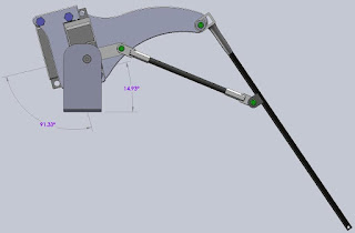
Now that the stability issues have been figured out and I am happy with the amount of force I can get out of the linkage, I think it's time to get a better idea of what I have built. I am reasonably confident that 4 or more of these mechanical legs mounted to a base of some sort could be controlled well enough to make the entire contraption to walk so I took the time to model in SolidWorks the leg mechanism as it is today. The black carbon fiber leg tubes and the ball joints are all defined so that I can move the leg in the CAD software and accurately measure the rotational angles of the Futaba servo motors at any leg position. To walk smoothly both servos need to move at the same time to take a step due to the linkage mechanism. The tip of the leg (the foot essentially) should move in a reasonably straight line as the leg takes a step otherwise the robot will waddle and jerk as it goes along. Probably not a big problem at first but eventially if the robot gets some kind of sensor system to monitor where it is the waddle and erratic motion could be a problem. I can think of a few other ways than CAD to figure this out like move the actual prototype leg and try to measure the angles or open up the servos and measure the resistance of the position pots that are inside.

The two Futaba servos are mounted on top of one another with the top one causing the entire leg to Rotate down and the bottom one (by linkages) causing the leg and foot to extend. There are two aluminum plates that and on the ends of the servos and spaced apart with aluminum and plastic standoffs. I went with this approach to keep the amount of metal bending to a minimum which should make these more rigid.

The pivots or bearings are made from nylon standoffs that happen to fit nicely into K'nex pieces with a little bit of cutting. The loose fit and the low friction make good bearings. The attach points to the carbon fiber tubes took a bit of experimentation but I settled on bending some metal, wrapping it onto the carbon tube in an area that had been sanded, wrappint it up with fishing line and the spreading clue over both the metal and the line. Before the glue dries sliding heat shrink tubing over all of it and heating - shrinking it down. This seems to have made a reallt strong bond to the tube and is working well.
 I have created some relationships in the CAD model that I can control with dimensions and measure the angles as the foot moves. All the angle information and the actual foot position will go into a spreadsheet to define a state machine based on the combination of servo rotations. Put another way the table will be a look up of servo angles with the result being the location of the foot in 3D space. This table or the data simplified to a formula will go into the robot controller that will eventually run this thing.
 This is a lot of information and I am tired so I am sure it's not making a lot of sense the way. Eventually it will all work.... ;-)

Tuesday, August 25, 2009
Stability problem solved...

After thinking a bit about the Stability Issues with the robotic leg I decided to do some more experiments and try to reproduce it at various angles and orientations of the leg mechanism. I Rotated and Extended the leg to get it into a position that was causing a great deal of instability then held it in my hand. I tried rotating it upside down while poking it with my finger to get it to resonate and shake. It seemed to do that in all orientations and positions... so I get the feeling that it isn't just the balance issue although that is part of it. While moving it around I noticed that applying some pressure on one of the servos, essentially fighting the motor caused some jitter in the other one. This had to be a power supply issue so I put my oscilloscope on the power then signal wires and could see the jitter in not only the servo position command signal but in the power supply as well.... Looks like the little Futaba servos pull a lot of current and are messing with the control circuit I built. To isolate the problem I separated the power supply wires for the motors and the control circuit and then powered the control circuit from my home made triple output bench top power supply.

That seems to have fixed the servo jitter problem for the most part! There is still some instability but that appears to be related to the servos and inherent in their design (still learning about these) I should have run a dual supply from the beginning but I'm thinking long term as in a mobile Robot device that would only have one power supply for everything. Although I am reconsidering that now at this point!
In summary I believe that what was going on is a combination of several things: 1) The servos are a bit jittery due to their design and low cost 2) The natural resonating frequency of the leg is near the 'jitter frequency' 3) The single power supply and the common wiring was injecting noise into the control circuit 4) The noise caused the servos to jitter and oscillate more 5) Because of number 1 and 2 above the entire system was feeding back on itself 5) Certain orientations and balance exacerbated the problem.
I'm going to test for that and be sure that the leg will function in all orientations then add the Turn servo to the mechanism.
Monday, August 24, 2009
Leg Prototypes 1 and 2 along with a Servo Exerciser, Power Supply
This is basically the first post documenting the design, construction and testing of a robotic leg mechanism that will (someday) be used in a home made robot. I have been messing around with the idea of building a robot using servo motors commonly used in RC boats and airplanes etc... I am using Futaba S3004 servos and fabricating linkages and bearings out of plastic and some RC ball joints. The idea here is that 4 legs can be built using 3 servos in each leg. These could be mounted to a square base with one in each corner and made to walk etc... using a small single board computer like a Basic stamp or something similar.
Before starting on the base or getting a processor board I decided to pick up a few servos and figure out if the legs would even work. Below is what I have been doing in the leg design so this post is kind of a catch up to where I am today. I'll post CAD files of a finished design once I work out all the bugs.
In each leg one servo will lower the leg in what I am calling a Rotate move. Another servo to extend the leg using a linkage mechanism - an Extend move and eventually a third to turn the leg in a Turn move. Because I started this blog a few days after I started constructing the legs this post will lay out some of the previous work. I have no experience with these types of servos so I am learning about their characteristics.
In each leg one servo will lower the leg in what I am calling a Rotate move. Another servo to extend the leg using a linkage mechanism - an Extend move and eventually a third to turn the leg in a Turn move. Because I started this blog a few days after I started constructing the legs this post will lay out some of the previous work. I have no experience with these types of servos so I am learning about their characteristics.

I built one leg prototype without the Turn servo just to test the linkage mechanism. The picture shows the leg lowered about 45deg. with a Rotate move. The extend linkage is out about half way as well. The total travel with these servos is 180deg. In this design the Rotate servo is held stationary and the Extend servo moves with the linkage in a Rotation. In this way the total mass being moved in a Rotation is the leg mechanism and the Extend servo combined. The center of gravity in this design made it a bit lopsided in the Rotate move as the center of gravity moved over the Rotate axis. The Rotate servo oscillated as the leg went 'downhill' and had gravity helping it. It was stable in the other direction.
Last night and this evening I finished assembling the second leg prototype. I tested it and it exhibits some of the same issues as prto #1 did with stability in the Rotational move. In this design I put both the Rotational servo and the Extend servo in the linkage mechanism. In this way both servo motors and the leg linkage move when a Rotational motion is done. This design is balanced when the mechanism is horizontal as shown in the picture. (Prototype 1 is on the left in the picture for comparison, Prototype 2 on the right) This leg too has some stability issues when it is balanced as shown, the Rotation servo seems to be susceptible to oscillations when touched or poked a bit. Also when the Extend servo is operated and the leg is in this position the motion of the Extend movement can initiate the oscillations.

One thought is that the moment of inertia for both leg prototypes is the about the same and the natural resonating frequency of each mechanism is approximately the same (I'm guesstimating anyway). If this frequency is the same as the internal servo feedback loop that could cause the instability. I experimented with a cantilevered pole attached to one servo on the bench and was able to get it to oscillate by changing the pole length until I found the "sweet spot". In this experiment the axis of rotation was vertical and the pole essentially laying flat and rotating horizontally so gravity/balance wasn't an issue. Another option is to drive the leg mechanism in the Rotation move by using a linkage to connect the Rotation servo to the leg rather than mounting the leg directly to the servo. The linkage will take the mass of the leg off the servo head couple it to the servo through the linkage so the reflected inertia of the leg mass back to the servo can be 'set' by changing the linkage arm length. If I build and test the linkage approach I'll post a picture to explain it better.

Before building the legs I built a small servo control box. You can see it in the picture above, it's the silver metal box behind Prototype 2 with three knobs on it. This box controls up to three servos, turning the knob causes the servo to turn by the same amount. (Because the servo motors only turn 180deg the knobs don't turn all the way around) The schematic is a hand scribbled mess but what I built from it works. There are a billion different schematics on the web showing similar circuits but I built mine mostly using parts I had laying around the garage. There is nothing new or interesting about the circuit but I put a copy here in case it stops working and I can't find the paper I scribbled it on!!!
Sunday, August 23, 2009
Subscribe to:
Posts (Atom)