Links to stuff on this blog

Use the Site Index of Projects page link above for an easier way to find stuff on my blog that you might be looking for!

Wednesday, September 30, 2009

The Low Down On Homemade Tops....

Here is another fun lathe project that I did and unlike the Multicenter Lathe Statue this one has some actual practical use! I decided after some suggestions by Otto Jr. and Matt Mylar that I should try my hand at making some tops on my Homemade Wood Lathe. The top was a pretty straightforward project with the only really tricky part being the metal point at the tip that the top spins on.


The above picture is how the top turned out on the lathe (pun intended). The wood that I used is one of my favorite types to use for turning practical stuff  - bamboo. These days you can go to the local discount store and get laminated bamboo cutting boards for cheap. There are also some expensive ones out there that you can get that have some advantages that I'll mention. These boards are made up of small pieces of bamboo that have been machined smooth into strips and then the strips glued into a board. I have found bamboo to be a relatively easy wood to work with that has basically no grain and is easy to sand. Although when sanding bamboo (or anything for that matter) make sure you have some dust management system and wear a face mask. The difference between the cheap boards at the discount store and the more expensive ones is the cheap ones tend to have voids and empty spaces inside them in random places. You can't see the voids until you cut into it but be aware that they might be there if you decide to chop up your bamboo chopping block.


So after getting the bamboo boards I got a hole saw and cut small discs out of the them . Then I glued all the discs together into stacks. I drew black lines on each disc to show where the grain direction was and made sure that when gluing the stacks together the black lines didn't line up. In this way the grain is at right angles in each layer. It's actually a bit more complicated because the cutting board alternates layers of bamboo and those are also at right angles... but simply put they are not lined up.
  
In order to mount the stacks on the lathe I had to glue each stack onto a piece of base wood that I could use to mount to the lathe spindle. In the above picture there are two stacks glued and dried with one on the lathe.


Turning the top down to the classic top shape was easy and a lot of the fine shaping I did with a wood rasp. The lathe gouge is handy for big cuts but finer detail is easier if you use a file or rasp and essentially power sand/file it into shape. A measured drawing of this project is available upon request if you want to know the shape!


Once the shape is right sanding and waxing the top is next. To get the top off the base plate I just law a saw blade against the place I want to cut and turn the lathe on. I don't recommend anyone using a saw blade like that or a wood file to shape stuff on a lathe. Be safe and don't do what I do!
The point of the top I made with a screw that I glued into a small hole that I drilled in the end of the top. Onto the screw I threaded a small aluminum shoulder nut and glued that too. Again I grabbed the file and filed the screw to a point.
Tops are fun if you can figure out how to wind the string onto them and throw them. Some people are good at it and others not so good. I am better at making tops than throwing them I think.


Tops when left alone like to conversate amongst themselves as shown in the above picture. Leave them alone while they are conversating or until the urge to throw one becomes too great and you must do it. If this is the case use caution when approaching the tops and it's wise to make a low whistling or humming sound as you approach so as not to surprise them. Stampeding tops can be dangerous as they have a sharp point on one end (the bottom).


The picture above shows a bit of the point that is made from a filed down screw and the aluminum shoulder nut. The shoulder is important to keep the string from falling off the top as you wind it. I did consider making that shoulder on the lathe from wood and just put a metal point in it but I didn't think that it would be strong enough. Repeated throws and impacts with cement or roadway and it would be chipped and broken off.
There you have it:
- The Low Down on the Homemade Top -

Saturday, September 26, 2009

Electric Hub Motor Bicycle Prototype... not much to write about but pretty pictures included

A short time ago I had the opportunity to get a good deal on an electric wheel hub motor for a bicycle. These motors are built into the hub of a bicycle wheel where the spokes attach. At the time that I got it I didn't have a bicycle but I thought it would be something fun to have around the house. Well not really... right after I got the electric hub motor I went out to Target and bough a bicycle for $95.00. I don't know a whole lot about bicycles or what all the correct names are for the various parts in a bike, but I did build an electric bike and at the same time designed a rear dropout. Don't get upset if I don't know what I am talking about when it comes to bike stuff... just post something angry in the comments.  As I mentioned in the title of this post there isn't a whole lot to talk about but I do have some nice pictures!


The electric hub motor is made by a German electric motor company Heinzmann and is spoked into an Alexrims DM18 rim. I gather in talking to people that both the wheel and the rim are much better than the bike that I bought at Target. I don't feel too bad about this - having good expensive wheels on a crappy bike - because where I live almost everyone has a $900 piece of crap car with $3000 spinning chrome rims on it. At least I look super cool on the bike and they all look like idiots.
 
Anyway the aluminum box that I hose clamped into the frame holds the 12 volt SLA batteries (Sealed Lead Acid). There are three of them in there wired in series for a total of 36 volts. On the front of the aluminum box is a motor speed controller that is wired into the grip throttle on the handle bars. The grip throttle and the controller are both made by the same company and I got them with no documentation. I used a ohm meter to figure out which wire went where as far as the batteries and motor.


I got a small plastic box and added a couple of switches to switch a car battery charger to each SLA in succession. In other words I can charge each battery individually and then when the charger is disconnected they are all drained in series to run the bike. Mostly this project was just piecing together some parts. I had to get a single speed freewheeling sprocket for the Heinzmann Hub Motor to get it to fit into the bike. Other than some shimming and spacers the whole thing took less than a week to put together. With the rear single speed sprocket I just have the three front gears so the bike is a three speed + the motor.
  
Once fully charged I can make a round trip to the post office of the supermarket on one charge and just a little pedaling at an average speed of 20mph. I think if I got newer batteries instead of the used ones that I have it would get a bit more distance. As the price of gas has come back down a bit I'm not as eager to tinker with this but it is something that I will mess with. One thing I want to do is now that I know it works I'm going to make a cover for the aluminum box so it's sealed and I'm going to paint it blue like the bike.


During the construction of the bike I designed a rear dropout for another bike project that a friend of mine is doing. The CAD model of the dropout is in the picture above and he helped me get the parts for the electric bike. UPDATE: I made a post showing the bike this dropout is used in HERE Check it out!


Now I have told you everything that I know about bikes. When I get around to cleaning up the electric prototype pictured above I'll put up some more pictures...

Tuesday, September 22, 2009

Robot Base Mechanics

Finally after much filing, cutting and drilling the 4 legs are assembled to the robot base. As mentioned in other posts and to summarize here the base is made from an Epson printer cover and each leg is built from 3 Futaba S3004 (or in some cases S3003) servos. It took some time to get the whole mess to this point, mostly because of other life things getting in the way, but now that it is done (partially) I can take a break and focus on the electronics.


When positioned carefully the legs can support the weight of the assembly and be stable without falling over and without power. I am considering using this position as a generic starting position to power up from but having the base sit flat on the floor might be better. With the base sitting flat on the floor the challenge would be to get the legs under control and the entire thing to stand up. Once standing up of course getting it to walk without falling over would be next.


At this point there isn't a lot left to do mechanically other than routing the servo cables so the don't get tangled as the legs actuate. While I am doing that I'm going to be looking into servo controllers and the software needed to control them. Initially I'm planning on just having a "serial to servo" converter on the robot with an umbilical connecting it back to a computer and a power supply. I'll use that set up to debug most of the motion and work out walking. The eventual goal will be to have a processor board with batteries on the robot so it can move autonomously but until I can figure out how to make it move a remote PC to control it will be easier. Why do anything the hard way?


Sunday, September 20, 2009

More Legs and Some Progress ( or More Futaba Servos Assembled...)

This evening I have a bit of an update on the construction of the robot.  It may seem like this is taking a long time to build but the project itself isn't taking too much time (all things considered) I'm just not finding a lot of time to work on it. I did manage to get all four legs built up. As mentioned these are using mostly Futaba S3004 and a couple Futaba S3003 Servos that are inexpensive and so far easy to use.  The only difference between the Futaba S3003 and the S3004 is the 3004 have bearing and not bushings. Each leg consists of three servos in total giving each leg what I call Turn, Rotate and Extend motions. It's pretty irrelevant what I call each axis of motion but for now I'm sticking with those names. In the last update that I posted I had a picture showing the plastic base that I cut from the top cover of a desktop Epson printer.


This shows more or less how I intend to have the legs sit but there are only three legs in the picture. I am happy to say now that I have the fourth leg built up using the Futaba's and I also have all the turn brackets fabricated for all three legs that I mentioned in the Aye Robot post. Also I figured out a couple of issues in building up two of the legs as 'mirror images' of the initial prototype leg. Anyway here are all four if full color for your enjoyment:


As mentioned these are all using Futaba S3004 servos (mostly a couple of Futaba S3003's as well). The orange colored parts on the end are cut pieces of K'Nex that I used as bushings. There is a 4-40 screw holding a nylon spacer that runs in the center hole of the K'Nex acting as a bearing (bushing technically). On the bottom of each Turn bracket I mounted the round disc Futaba Servo Horn that comes with the Futaba in the box when you buy it. That servo horn will allow each one of the above legs to mount directly on top of yet another servo that is mounted in each corner of the 'hacked' Epson printer top. I took a picture to help explain a bit better what I mean.


In the picture you can see one of the Futaba S3003's sitting in the corner of the printer top that I'm now going to start calling something like 'robotic base chassis' instead of Epson printer top. Maybe 'Base Chassis' is better and shorter. Anyway on the bottom of the leg assembly you cab see the round Futaba Servo Horn screwed to the Turn Bracket with a couple of 4-40 screws. Immediately remaining at this point is cutting 3 more holes on the Base Chassis to mount the Futaba's in and figuring out a way to secure them in those holes. Right now I am thinking of cutting up the remaining pieces of the printer cover and gluing them onto the Base Chassis to provide screw points for the Futaba's.

I need to give it a bit more thought but maybe metal brackets would be better than glued plastic.


Wednesday, September 16, 2009

Home Made Wood Lathe or a DIY Wood Turning Machine

Awhile ago I decided to build myself a Home Made Wood Lathe. This is another one of those projects that I wasn't sure was going to work and would require quite a bit of effort up front before I could see if it was going to work. Fortunately it did.
  
UPDATE 8/22/10: I've added a NEW POST HERE detailing the Lathe Headstock design and the Lathe Motor Speed Controller! Click the link if you are interested in the design details. I have a video clip HERE on my YouTube channel explaining this lathe in greater detail.
 
Finished Homemade Wood Lathe
 
Everything on the lathe was acquired in the 'home made fashion' or in other words it's all stuff that I scrounged up from junk piles or had laying around the garage at the time. There are a couple of things that I did have to buy but my out of pocket expenses for this project was less than $50.00. I can turn projects up to 20" in diameter and 36" long although spinning material that big is scary even on a "real" lathe so I don't often make stuff that big.
  
The wood that makes up the frame is from old shipping pallets that I took apart then planed down smooth and straight. They started out a 4 X 4 but are now a bit smaller! The edges of the legs I left square but the bed rails have rounded edges to help the tool rest saddle and the tailstock saddle slide a bit better.
Detail of DIY Lathe Headstock

The drive system is made from a DC servo motor that was thrown away by my employer at the time. I used a hose clamp to hold it down to a cross member in the leg section. The cross member is slotted  vertically to allow for tensioning of the drive belt. I had my doubts about how well this was going to work but I've been running this now for almost 8 years and I have never had to tension the belt or mess with the motor. There is a Vee Belt connected to the servo motor that drives a second bigger pulley connected to the spindle in the head stock. This gives a decent gear ratio so I can keep the servo motor spinning faster than the spindle. This is important because although the motor is a DC servo there is no closed loop control system of speed control - no feedback from the encoder in the motor. Because of this it's tough to get the motor to turn slow under load at a constant speed, geared this way the motor goes fast with the spindle at a slower speed.
The slower turning speeds are handy when sanding, waxing and polishing work that has already been turned.
 
The spindle is actually a hollow piece of chrome-moly steel pipe that is set in two bearings that I seated into the vertical post that makes up the head stock. The inner diameter of the pipe is slightly bigger than 5/8" - I filed and sanded it to get it to that diameter (more about why later).  There is a snap ring groove that I cut with a hack saw on the work side of the pipe. The snap ring prevents the pipe from slipping all the way through the bearings. Between the pulley and the outer bearing there is a spring that sits on the outside of the pipe pushing against the pulley and the inner race of the outer bearing.

Tool Rest and Work Area of Homemade Wood Lathe
 
The spring is there to keep tension on the bearings holding them together in the head stock post. Essentially the spring is trying to pull the pipe through the headstock away from the work but the snap ring prevents that so the whole mess in in compression clamped to the headstock post. Maybe I'll draw a cross section of it someday if anyone asks, because my description of what is going on is confusing I'm sure! UPDATE: I did details the headstock design because of emails from people and you can read about it HERE in this post. If you would like even more details email me at ottobelden@yahoo.com or leave a comment below.
  
The tailstock is the same concept and you can see the tailstock spring in the picture above on the right. The difference between the two is the tailstock is a solid rod filed down to a point and there is a nut on the outside end instead of a pulley. The tailstock and the tool rest shown above are clamped to the bed rails with a bolt between the rails for positioning adjustment.
  

Various Home Made Mandrels for the Lathe
      
The main mandrel that I use in the lathe is the lower right one. It was made by taking a 5/8-11 bolt and putting it through a pipe floor flange that has a short length of pipe screwed into it. I glued the pipe into the pipe flange and drilled a hole through the pipe and the bolt and pinned it so the bolt can't turn inside the flange without unscrewing the pipe. After doing that I glued two hardwood discs together and glued and screwed them to the floor flange. There are screw holes in the wood so that I can screw pieces to be turned onto the end so essentially the wood discs are the mandrel face plate. The 5/8 inch bolt slides nicely into the inside of the  spindle pipe in the headstock that I mentioned above. I filed the spindle pipe so that a 5/8 inch bolt would go in easily. I choose 5/8-11 as the bolt size because that is the standard thread on sanding discs and grinding wheels as shown in the picture above. I also wanted this lathe to be able to work as a sanding and grinding tool.
  
Sanding and Grinding Table
  
This is a fuzzy picture of a sanding and grinding table that I don't recommend anyone trying to build. It works fine but it is dangerous and tends to sand your knuckles at about the same rate is sands the work piece. In the picture the grinding disc is mounted in the spindle and the table is in front. The table is hinged so I can adjust it to various sanding and grinding angles with the window hand crank gizmo mounted underneath.  The window crank is one that I bought at the hardware store and is used on older homes that have windows that open out. You turn the crank and the bar connected to it moves the window open. I have it mounted sideways so turning the crank adjusts the table up and down setting the angle of the table relative to the sanding or grinding disc.
     
 
Click on the link Multicenter Turning Lathe Statue Project to see details on this project!
   
Lathe Motor Speed Controller
  
The motor speed control for the lathe is built into a box that is also made of wood but has a metal front and rear cover. The rear cover is louvered and came off an old clothes dryer and the front was too. I mounted a variac transformer inside on the front cover and some capacitors in there too. The variac allows me to control the voltage and therefore the speed of the lathe by turning the big black knob in the picture above. There is a reversing switch that allows the motor to spin in the opposite direction for sanding and a handy read light to tell me when it's on. UPDATE: I wrote a post with more details including a schematic of the Motor Speed Controller above. Click HERE to check it out!
 
Over the past several years this has been a useful tool to have and I have made a bunch of things with it. Honestly I'm surprised at how long it has lasted and how well it has worked all this time - definitely worth the time and $50.00 it took to build it.
  
Various Lathe Projects


Above are some of the things that I have made with my homemade wood lathe. Another handy thing to have if you are going to do any kind of woodworking is a dust collector. I built a dust collector out of "stuff" I had laying around that you can see HERE. If you would like to know more about the lathe or anything else let me know!
   
Click HERE to see some more Wood Lath related things...
Have a look HERE at some of the other (but not all) of the projects that I have written about!
   
HERE is a post by Leo Basic on his blog about a lathe that he made. He credits my design for some of his ideas in the construction but he did an even better job! - Nice Work Leo!
       
If you have any questions or comments please let me know below or send me an email at ottobelden@yahoo.com
   

Monday, September 14, 2009

Update on the Robot Building

This post is just a quick update on the progress of the robot that I am building. I have been busy with other things recently and have not had a lot of time but some progress has been made. I managed to get the third leg assembly built and part of the plastic base modified to mount the first leg. The third leg that I built is a mirror image of the first tow because I need what essentially is a left and a right set of two legs each. These will be in opposite corners from each other. So in the picture below the upper left corner leg is the mirror image assembly of the other two legs.
At this point I need to complete the last 'mirror image' leg and continue modifying the base. In the picture the lower left leg is sitting on it's rotate base, eventually all the legs will get similar bases. Under each base an additional servo motor will be mounted that will turn each leg independently.
There is still a lot of work to do but the project is coming along... some open issues still are the 'walk cycle' that the legs will have to perform in unison allowing the contraption to move without falling over and a big issue of getting the electronics working. As far as the walk cycle goes I believe there is enough motion and degrees of freedom in the legs to keep the center of gravity inside a triangular foot pattern (formed by three legs down on the floor) while the fourth leg moves. I'm still not sure this is going to work but I'm confident enough that I'll keep building and see what happens.

Wednesday, September 9, 2009

Multicenter Lathe Statue: A Experimental Test Project

Some time ago I decided to try Multicenter Wood Turning or as some write Multi-Center Turning. I'm not good with hyphens... I think If I ever get around to blogging about English Grammar it would definitely be filed in complaints. Anyway I wanted to try multicenter turning because it looked like a fun thing to do and figuring out how to turn something on a lathe using multiple set ups so the axis of rotation changes with each set up seemed fun. Especially considering that the work is off balance the entire time. Another thing I like to do is not spend money so rather than buying a nice big piece of wood that didn't have any knots I cut op various pieces of scrap and glued them together to make a bigger piece. I use this lamination technique often because it tends to create interesting patterns in the wood. So I glued it all up into a relatively flat piece then cut that piece at odd angles, drilled holes into the lamination and inserted wood dowel pins with more glue.
  
  
Cut and Glued Wood on Mandrel

Saturday, September 5, 2009

DIY Homemade Ranque-Hilsch Vortex Cooling Tube

Nothing really says Labor Day Weekend to me like a homemade vortex cooling tube! Well maybe not... but  I always wanted one and they really aren't that hard to make. I built one in one afternoon in the garage from PVC pipe, glue, a few tube fittings, a adjustable clamp and some sawing and filing...  The cool thing about them is there are no moving parts or high tolerance dimensions to hold when making your very own vortex cooling tube! All you need after building it is compressed air to get it to run and you get hot air out one end and cold air out the other. Here is how I DIY'ed a cooling tube and a little bit about how they work. The first picture below is what I ended up with. You can get anywhere from 10deg C to 70deg C cooling with these kinds of devices. I got about 15 C with mine but I bet I could get more if I tinker with it a bit.
UPDATE 8/28/10: I have added some videos explaining how I built this HERE!!
Check them out! 
  
Finished Vortex Cooling Tube
UPDATE 7/8/11 I made a smaller Vortex Tube and got much better results and posted info about building it HERE and well as a Video covering the construction HERE. I also created a Vortex Tube FAQ page HERE have a look at those pages if you are interested in building a Vortex Tube or if you just want to know more about them. Questions / Comments? leave some comments or email me at ottobelden@yahoo.com !!
   
These devices have been around for a long time and have some practical uses in industrial applications from sewing machines to welding. The principle of operation is that compressed gas at a significant pressure is sent into a tube through tangential holes or nozzles somewhere near the middle of the tube. Essentially these holes are going into the tube "right on the edge" so that when the gas enters it creates a 'swirling vortex' of gas. Sounds high tech!!! The gas swirls down the tube and there is a separation process due to the kinetic energy in the gas and you end up with cooler gas in the center of the tube and hotter gas on the outside. The cooler region can be and usually is cooler than the gas that entered the tube through the inlet nozzles.
  
  
Cross Section Sketch of What is Going on Inside

Here is a crude hand sketch I did of what is going on inside. The gas is going into the tube on the left hand side of the drawing through the holes labeled Inlet Air. The green spiral shows the gas swirling to the right where it runs into a conical shaped block that can be adjusted in and out of the tube. When it hits the cone the hotter gas is siphoned off around the outside of the cone and the cooler continues to spin back down the inside in the other direction. When the cooler gas makes it back to where the nozzles are it reaches an orifice in the tube that allows the cooler gas to exit out the left side in the drawing. The orifice is there to let the cold gas out but also to facilitate getting the inlet gas swirling and traveling in the correct direction (to the right in the picture). Adjusting the cone shaped block in and out allows you to adjust the ratio of how much air is going out each end of the tube - balancing the flow - and changing the temperature difference between the hot and cold ends.

To build my vortex cooling tube I used PVC pipe that has an inner diameter of about 0.81 inches. Looking into the formulas for the design of a "real vortex cooling tube" you usually want the length of the Hot End of the tube to be about 45 times the diameter or in my case about 36.5 inches. So this is the length in the drawing above from the inlet nozzles to the cone block valve. In keeping with that thought here are some other dimensions that I followed in making my tube:
  
Tube I.D. = 0.81"
Hot End Length = 45 x 0.81 = 36.5" (round off a bit)
Cold End Length = 10 x 0.81 = 8 (round off a bit here too)
Orifice Size = 1/2 Tube I.D or about 0.40 inches (ballpark rounding of slide rule accuracy)
Inlet Nozzles = 0.12" and I drilled 5 of them
  
Vortex Chamber

A close up view of the "vortex chamber" as I like to call it - this is where the Inlet Nozzles and the Orifice are. To make this part of it I took a piece of PVC tube and cut it to make the Hot End Length and the Cold End Length to the dimensions above. (Scroll down to a hand drawn picture of a cross section when reading this part to help see what I'm explaining) Then I got a thin piece of plastic and cut it into a circle the same diameter as the Outside of the 0.81 I.D. PVC tube -  the outside diameter was about 1.05 inches (so 1 inch tube). I drilled a hole in the plastic about 0.40 diameter to make the orifice. I then got a 1" PVC pipe tube coupling and filed and sanded the inside so that the PVC pipes will slide all the way through. I slid the Hot and Cold tubes into this coupling capturing the cold Orifice plate in between - no glue at this point.
  
Orifice Plate

Above is a picture looking down the cold end of the tube at the orifice plate. You can see the 0.40 diameter hole. I marked the Hot and Cold tubes as well as the coupling so I could take it apart and put it back together in the same orientation.... then I took it apart and glued in the hot tube only. Next I drilled 5 holes through the coupling and into the tube at an angle (tangential) as close to the end of the Hot tube as I could.
  
  
Actually I had my assistant Otto Jr. help me drill the holes! The drilling was made easier bu starting the holes with an Exacto knife.
 
  
UPDATE 8/28/10: I have added some videos explaining how I built this HERE
Check it out!


So now the two 1/4" cut pieces (red in the picture above) form the ends of a chamber labeled Inlet Air Area with the large 2" pipe coupling making the outside (Purple). All this is to have one inlet fitting for the air to go into the Inlet Air Area and from there it can make it into the 5 Inlet Nozzles. I could have had just one inlet nozzle or have five air lines into each hole but the method above works better and is super fun to make! I drilled one hole in the outer coupling and screwed a 1/4 Tube X 1/4 NPT fitting into the PVC plastic. I applied a lot of PVC glue and drilled the hole small so the fitting cut it's own threads going in.
  
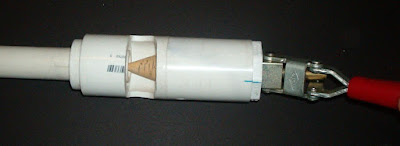
Now onto the other end of the vortex cooling tube. The cone block I turned down on my homemade lathe and glued a bolt into it. The bolt threaded into the end of a DeStaCo clamp that was run through a PVC pipe plug. I cut a notch in the tube to let the hot air out and drew graduations on the cone to get an idea of how much adjustment I'm getting when I move the red lever.
  
Here is the cone block valve installed in the end of the tube.
  
That's about all there is to it! I attached an air hose to the tube fitting I screwed into the side, put on my safety glasses and turned on the compressor. These things make a lot of noise and get pretty warm / cold on their respective ends.
   
Be sure to take a look at THIS link to see some of the other Vortex Tube related things (and other stuff) that I have built.
   
For another cool version of a D.I.Y. Ranque Hilsch Vortex Cooling Tubes and lots of good information click HERE
   

Thursday, September 3, 2009

¡Aye! Robot....

Working on the robot some more and trying to figure out a way to add the Turn Axis to the leg assemblies using parts that I have on hand... this is turning (no pun intended) out to be a bit difficult. I have four legs and I only have three bearings in my junk pile that have extended inner races and a flange to keep them in place. The second prototype leg that I built had a 'yoke' for the Rotate Axis that I made by bending some sheet metal. That worked fine for both prototypes in fact and can be seen pretty well HERE. Its the part that is acting as the base with the legs hanging over the table in the pictures.


I think some of the stability and jitter problems were enhanced by having this piece made in such a flimsy way and I'm sure that trying to make a robot walk using a piece like that won't work. In fact I am having some doubts if this think can ever walk! So to be sure that i was going to have something rigid enough to allow the legs to pivot and not bend and give I decided to use extruded aluminum box beam for this part. Besides I happen to have some extruded aluminum box beam laying around so i cut it in one inch lengths on the band saw.


The box outside dimensions are 3" X 1.5" X 0.125thk wall. Pretty hefty stuff for what I am doing but that is what I have laying around and the wall thickness is enough to drill and tap into. But just having it is one thing and figuring out how to mount a bearing (or make one) so that it can rotate is another. I'm still left with three bearings of the right size and four legs. Maybe I'll get lucky and find something that I can make some bearings out of or another approach. Still in thinking about the walk cycle and how much rotation I'll need is making me wonder if a four legged robot is going to be stable enough. Three points define a plane and keeping the center of gravity in the triangle means it won't fall over. But how will a four legged devise walk? I suppose that I will find out when it falls over the 40th time or so.


I cut one of the sliced box beam pieces and drilled and tapped. The leg assembly on the left sits in this and rotates down. The prototype sheet metal one is in the upper right of the picture and some shoulder screws and a bearing that would be perfect if I had more.


Meanwhile I'll keep building parts and putting stuff together. If I don't find anything laying around that I can turn into four bearings I'll break down and go buy some hobby bushings or bearings... Having three perfect bearings when I really need four is frustrating!


At some point soon I'll do a layout in CAD or on paper to work out how this thing will walk. I'm getting close to having a good idea of how much it will weigh and more importantly how high up the center of gravity will be.

Tuesday, September 1, 2009

Homemade Halloween Headwear from Bicycle Helmet

It's getting to be that time of the year when we need some stylish yet functional headwear. By stylish I mean no one else will show up at the party with one like yours and by headwear, I mean it sits on your head or quite possibly is glued to it! What I decided to do to make something new and trendsetting is buy one of those inexpensive children's bike helmets you get from Target or Wal-Mart. I'm sure you have seen them if you walk down the bicycle accessory isle. These are the ones that cost around $10.00 or so and are not much more than a foam core with a thin layer of hard plastic glued to the outside and a couple of chin / head straps attached. I picked one up along with some of that "spray - insulation - in - a - can" that you get in the tools department. Just to be sure I was going to be able to color coordinate my helmet later with my jacked I bought some spray paint.

After getting home and of course before trying on the newly purchased helmet I started to pull it apart. I didn't want to post a picture of the new helmet as some people don't like to see new stuff torn apart. Oh well...I bought it! So I can do what I want with it ;-) To give you an idea of what kind of helmet I am talking about HERE are similar helmets...

One thing I think I should mention is that any helmet once modified in any way is no longer useful as a safety device in any way. If you cut it, sand it, paint it or in any way modify it don't ever use it again for safety. What I am describing in this blog is for costume use only - only for looks in other words!!!

So... after separating the the shell from the foam core of the helmet I cut the shell into pieces and glued them to the foam core in new places. I wanted the helmet to appear to come down over the chin and cover the sides of the head a bit. Once glued in place I filled in all the spaces with the "spray - insulation - in - a - can" stuff.


At this point the helmet looked something like the picture above and so did I. That "spray - insulation - in - a - can" stuff is sticky, noxious and goes everywhere fast - really fast. Don't underestimate the power of that stuff or it's adhesive qualities. I got some on my pants and it will not come out. I haven't tried too hard to get it out of my pants because I'm still trying to get it off my forearms!! I wore gloves and old pants but as I mentioned that stuff goes everywhere!!!

After giving the insulation stuff time to dry I got a knife and a very coarse wood rasp. One of those rasps that looks like a cheese grater seems to work pretty good at removing insulation in key areas and shaping the helmet down to something that looks like a helmet and not a frog with warts. Once the general shape was the way I wanted it I sprayed on some bright red spray paint. It takes a bunch of light coats to really cover the foam because it is so porous.

The red is intended only as a undercoat because this in not a "4 alarm fire hydrant helmet" I'll cover the construction of one of those in the summer months when the weather is hotter. So in keeping with the stylish yet functional headwear goal I sprayed a swatch of green above the brow as can be seen in the picture. This looked good and would be even better with some black!!

I applied several coats of very light green and very light black from various angles over the red base coat being careful not to fill in the pores of the foam. I wanted those to have some red left in them. Once there was more green and black than red left showing I let it dry overnight. The next day with all the paint good and dry there was quite a texture contrast between the shaped foam areas and the smooth hard plastic areas. To give it a more even look and texture I got a generic spray bottle and filled it with water. I set the nozzle to mist and sprayed the helmet until little drops of water formed on the smooth surfaces of the helmet.

Before the water had time to dry I sprayed the entire thing with several very light coats black spray paint. The very light coats is done to not have the spray paint blow the water drops all over the place. The several coats is to get a bunch of paint on the water drops and more importantly between the water drops. So the paint sticks to the areas between the water drops and not to the drops. I set the helmet in the sun and let it dry about 15 minutes or so.

With a dry cloth I very lightly wiped the water off picking up the black paint that was in the water along with it. What was left was the paint in between the water drops. I placed the helmet back in the sun for a couple of hours to dry it off really well. Then once it was really dry....

I did the same water mist treatment and spray paint coats but this time with green, let it sit, wiped it off, then  back into the sun for a couple of hours to dry it off really well. Then once it was really dry....

I did the same water mist treatment and spray paint coats but with the black paint. You get the idea here I hope. Each time the water mist covers the surfaces the drops are in different places so each coat of paint sticks in different areas. Once you have done this a bunch of times you get a really random and coarse looking surface. This is a technique that is easy to do and on a helmet that begs for the natural and worn look is fine. I have seen cars painted with this water technique and they look great - but to refine it to that level takes a lot of practice.

Anyway before I get off topic with the paint thought that is the home made do it yourself  Halloween helmet made from a bicycle helmet.